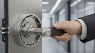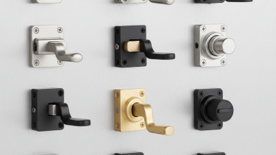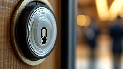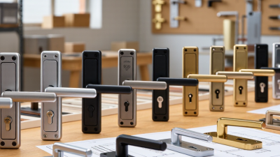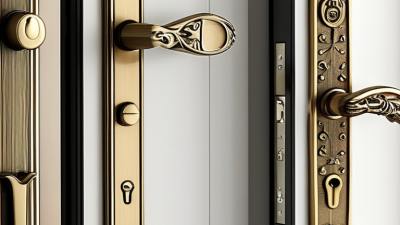
A Pull Lock may look like a simple handle, yet it performs several precise tasks. It pulls a latch, compresses a seal, and holds a panel firmly against its frame. You may find this mechanism on cabinets, access doors, toolboxes, vehicles, and industrial enclosures. Its value becomes clear when a door must open quickly but remain secure during vibration, pressure, or repeated use.
Locking-systems author Graham Pulford offers a useful principle: “Security begins with controlling movement, not merely hiding the keyway.” This idea explains how a Pull Lock works. The user applies force to the handle. An internal cam or rod transfers that movement to the latch. The latch then releases from its keeper. When the handle returns, a spring or linked component restores the locked position. Some designs include a key cylinder, padlock point, or electronic release for added control.
Small details matter. A loose mounting screw can create rattling, uneven compression, and premature wear. A misaligned keeper may make the handle feel stiff, even when the lock itself remains functional. This is where real-world experience complicates neat diagrams. Manufacturers describe smooth operation, but dust, cold temperatures, damaged seals, and hurried installation can change performance.
This guide examines Pull Lock construction, operating steps, common applications, and practical maintenance. It also considers limitations. No locking device should be judged by appearance alone. Material strength, installation quality, load direction, and service conditions all influence reliability. Understanding those factors helps readers select, install, and inspect the right Pull Lock with greater confidence.
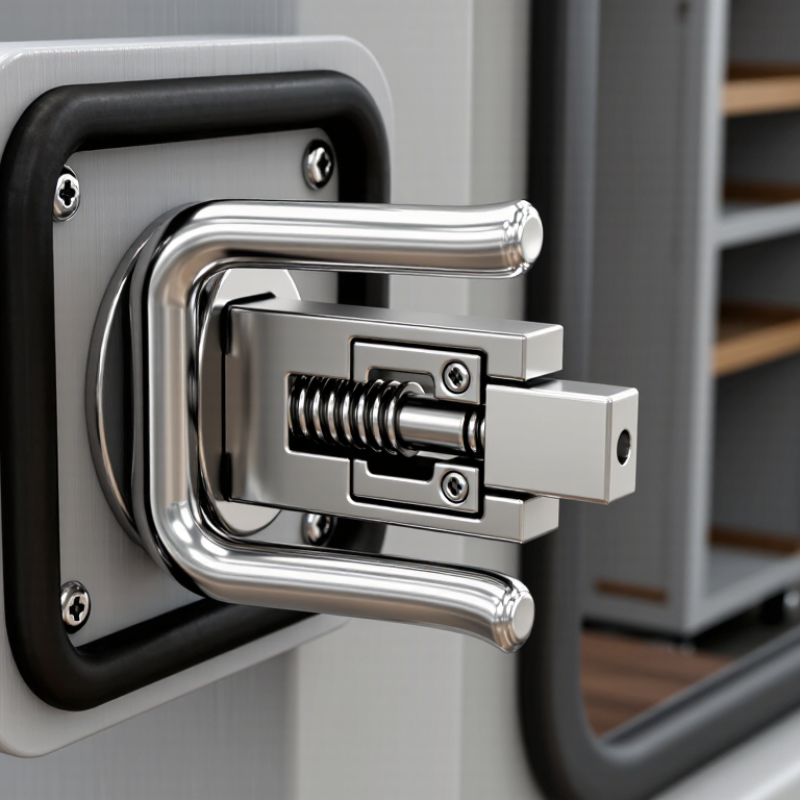
A pull lock is a door locking arrangement operated through a pulling motion, usually at a handle, pull, or connected mechanism. The term is not perfectly consistent. In some hardware schedules, it describes a lock integrated with a pull handle. In others, it means an auxiliary lock securing a sliding, glass, cabinet, or service door. That difference matters. A specifier should confirm the product drawing, door thickness, handing, cylinder type, and required security level before ordering.
Its purpose is simple: hold the door closed, resist unauthorized opening, and release smoothly with the correct key, thumbturn, or access device. Inside the door edge, a bolt or latch engages a strike in the frame. Pulling the handle transfers force through the spindle or linkage. Proper strike alignment keeps the bolt from scraping. Small errors matter. A loose pull can create noise, poor return action, and premature wear. Field checks should include clearances, fastener tightness, bolt projection, and operation under real door pressure.
ANSI/BHMA A156.5 addresses auxiliary locks and related door hardware, including performance classifications, testing, and dimensional considerations for covered products. It can support evaluations of durability, security, cycle performance, and installation compatibility. However, “pull lock” is not automatically a precise A156.5 category. Coverage depends on the lock’s construction and intended function. Review the current standard and neutral test documentation with a qualified hardware professional. Do not rely on appearance alone. A compact pull lock may look suitable yet fail to match the frame, strike, or duty requirement. Good specifications state the application, mounting method, bolt type, keying needs, and applicable A156.5 classification.

A pull lock is a compact locking assembly used on doors, cabinets, access panels, and equipment enclosures. Its handle provides a firm grip and transfers pulling force to the latch. When the cylinder is turned with an authorized key, the latch retracts or releases. Fit matters.
The latch is the moving part that secures the panel. It must extend fully into the strike, which is the fixed receiver mounted on the frame. A properly positioned strike prevents scraping and reduces movement during operation. Even a small alignment error can cause stiffness, noise, or incomplete engagement. In field inspections, I check the latch contact pattern instead of relying only on the key turning smoothly.
The cylinder controls access by locking the handle or connecting it to the latch mechanism. Its housing should sit firmly, without unwanted rotation or looseness. Retaining hardware includes screws, nuts, clips, washers, and internal brackets that hold each component in place. These parts may look minor, but vibration can gradually loosen them. Small parts matter.
For reliable operation, I examine the handle return, cylinder rotation, latch extension, and strike alignment together. Lubrication may help, but it cannot correct a bent latch or weak mounting point. I have seen installations that worked well at first and became unreliable after repeated use. That experience is a reminder to inspect the whole assembly, not just the visible handle.
A pull lock secures a panel, cabinet, gate, or access door through a simple mechanical sequence. In the locked position, a spring-loaded bolt or hook sits inside a keeper. The handle looks passive, but it stores the key movement. When the user pulls it, the handle rotates an internal cam. That cam draws the bolt backward, clearing the keeper and allowing the door to open.
Pull, retract, open.
The motion should feel smooth, not loose. Once the handle is released, the return spring pushes the bolt toward its original position. As the door closes, the keeper guides the bolt into alignment. A firm click usually confirms relocking.
It is not perfect every time. Dirt, sagging hinges, or side pressure can stop full engagement. A practical inspection should include a visual check and a gentle pull test after closure.
Industry demand also reflects the value of dependable hardware. Grand View Research estimated the global door hardware market at about USD 17 billion in 2023, with continued growth expected through 2030. The BHMA A156.13 standard evaluates lock performance through repeated operational testing, emphasizing cycle durability and secure engagement. NFPA 80 also supports regular inspection practices for applicable opening hardware. These references do not replace the manufacturer’s installation instructions. They provide a professional baseline. Small details matter, especially the final few millimeters of bolt travel.
A pull lock is a compact locking device operated by pulling a key, knob, or handle. Its security depends less on appearance than on the cylinder, bolt, mounting, and surrounding material. Basic wafer or spring-latch pull locks suit low-risk drawers and indoor cabinets. They are convenient, but their thin housings can offer limited resistance against torque and drilling. Pin-tumbler pull locks generally provide stronger key control and better resistance to casual manipulation. High-security versions may add hardened components, restricted keyways, or anti-drill protection. The difference is visible at the workbench: a weak lock may flex while the cabinet panel bends first.
UL 437 testing provides a more useful comparison than marketing language. The standard evaluates key-operated locks through tests involving picking, drilling, sawing, wrenching, and forced operation. Passing the test does not make every installation secure. Poor screws, thin sheet metal, or exposed fasteners can still create an easy failure point. UL 437 is also not a universal numerical security score; test scope and construction details matter. The FBI Crime Data Explorer recorded an estimated 847,522 burglary offenses in 2023, showing why physical protection still deserves practical attention. For higher-risk cabinets, choose a pull lock with documented UL 437 compliance, reinforced mounting, and controlled key duplication. I have found one detail easy to overlook: the lock may survive testing while the cabinet around it does not.
Pull locks secure a door, cabinet, gate, or access panel by engaging a locking mechanism when the cylinder or handle is pulled, turned, or released. Security depends on key control, resistance to covert entry, resistance to forced entry, and whether the lock has been independently evaluated.
The chart uses a comparative feature-coverage index from 0 to 3, not a certification score. A UL 437 evaluation indicates that a qualifying key lock has been assessed against specified attacks such as picking, drilling, sawing, pulling, prying, and wrenching. UL 437 is a testing standard, not a universal security ranking for every pull-lock design.
A pull lock combines a fixed pull handle with a locking mechanism. Pull the door from the outside, then release the latch with a key, thumbturn, or access control device. Its real performance depends on alignment, strike depth, fastener strength, and repeated loading. A loose pull can make a reliable lock feel defective.
Installation should follow the door manufacturer’s template and the applicable ANSI/BHMA test category. For mortise-style locksets, ANSI/BHMA A156.13 Grade 1 testing commonly requires 1,000,000 operating cycles. That figure is a laboratory benchmark, not a guarantee for every installation. During commissioning, technicians should record latch projection, door gap, closing force, and key or trim operation. Use a cycle counter when possible. Inspect the strike after several thousand cycles. Bright metal dust or fresh scoring can reveal misalignment early. I have found that small hinge movement often causes larger lock problems than expected.
Tips: Keep the pull square to the door face. Tighten fasteners evenly. Test with the door fully closed. Repeat checks under normal temperature and humidity. Do not rely on one successful opening. A Grade 1 result reflects controlled testing, while field conditions include slammed doors, warped frames, and neglected maintenance. The gap deserves attention. Each inspection should compare actual readings with the project specification and the relevant BHMA performance report.
| Category | Test or Installation Dimension | Reference Data | What to Check | Expected Result |
|---|---|---|---|---|
| Operating Principle and Installation | ||||
| Operating principle | Pull action | A pull lock uses a handle or pull to retract a latch, bolt, or locking mechanism. Releasing the pull allows the mechanism to return to its secured position. | Operate the pull through its full travel without forcing or twisting it. | Smooth, complete engagement and release |
| Lock engagement | Latch or bolt alignment | The locking element should enter the strike or receiver without rubbing against its edges. | Close the door or panel slowly and inspect the contact points. | Full engagement without scraping, bounce-back, or partial locking |
| Fastener installation | Mounting security | Fasteners must be tightened to the hardware manufacturer’s specified torque. A universal torque value does not apply to every pull-lock design. | Check for loose screws, movement at the mounting plate, or distortion of the housing. | No visible movement or fastener back-out |
| Strike position | Horizontal and vertical alignment | Alignment should be verified with the door or panel in its normal operating position, including the effect of hinges, seals, and load. | Confirm that the latch or bolt is centered in the strike opening. | Consistent engagement throughout repeated operation |
| Clearance | Moving-part clearance | There should be no interference between the pull, lock body, door edge, trim, strike, or surrounding panel. | Inspect at both the fully open and fully closed positions. | No contact except intended latch-to-strike engagement |
| BHMA Grade 1 Cycle Reference | ||||
| Durability benchmark | BHMA Grade 1 cycle performance | Grade 1 lock hardware is commonly evaluated against a 1,000,000-cycle durability requirement under the applicable ANSI/BHMA product standard. | Verify the exact BHMA standard applicable to the specific pull-lock type before testing. | Use the applicable product standard as the governing pass/fail document |
| Cycle definition | One complete operating cycle | One cycle consists of operating the pull and locking mechanism through its normal travel and returning it to the secured position. | Use the same travel, speed, load, and door or panel condition for every cycle. | Repeatable operating sequence |
| Initial condition | 0 cycles | Record baseline alignment, operating force, latch engagement, visible condition, and fastener security before endurance testing. | Photograph the installed assembly and record the initial measurements. | Baseline data recorded |
| Early inspection | 250,000 cycles | This is a practical interim inspection point for detecting early wear; it is not a substitute for the applicable BHMA test procedure. | Inspect wear surfaces, mounting points, return action, and engagement depth. | No cracking, loosening, binding, or incomplete locking |
| Midpoint inspection | 500,000 cycles | Half of the 1,000,000-cycle Grade 1 reference benchmark. | Repeat the baseline measurements and compare operating behavior. | No unacceptable change in function or security |
| Late-cycle inspection | 750,000 cycles | A practical pre-final checkpoint used to identify progressive wear before the end of the endurance sequence. | Check latch return, strike contact, pull movement, and fastener retention. | Mechanism remains fully functional and aligned |
| Endurance completion | 1,000,000 cycles | Completion of the commonly cited BHMA Grade 1 durability benchmark for applicable lock categories. | Perform a complete functional, visual, and security inspection after the final cycle. | No failure of the locking function or required operation |
| Performance Checks and Records | ||||
| Operating force | Pull or actuation force | Record the force required to operate the mechanism using the same measurement method at every checkpoint. BHMA limits vary by hardware category and test method. | Compare each reading with the baseline and investigate any sudden increase or unstable result. | No binding, sticking, or unexplained force increase |
| Return action | Handle and latch return | The pull and latch should return to their normal positions after release without manual assistance. | Release the pull from several operating positions and observe the return movement. | Complete and repeatable return |
| Security function | Locked and unlocked states | The lock should clearly distinguish between the locked and unlocked conditions and prevent unintended release when locked. | Test the mechanism with the door or panel closed and apply normal operating pressure. | No unintended unlocking or incomplete locking |
| Wear inspection | Visible damage and deformation | Inspect the pull, lock body, latch or bolt, strike, fasteners, springs, and mounting surfaces. | Look for cracks, bent parts, excessive play, corrosion, sharp burrs, and abnormal wear patterns. | No damage that affects operation, alignment, or security |
| Environmental condition | Temperature, moisture, and contamination | Record test conditions because dust, moisture, temperature, and cleaning chemicals can affect operating performance. | Keep conditions consistent and document any exposure outside the intended service environment. | Results interpreted together with recorded test conditions |
| Maintenance record | Lubrication and adjustments | Use only maintenance materials and procedures approved for the specific hardware. Unapproved lubricant can attract dust or affect internal components. | Record the product type, quantity, date, and reason for every service action. | Complete and traceable service history |
| Note: The 1,000,000-cycle figure is a commonly used BHMA Grade 1 durability reference for applicable lock hardware categories. The exact test sequence, loads, tolerances, force limits, and acceptance criteria depend on the specific ANSI/BHMA standard and product classification. Always use the applicable standard and installation instructions for formal certification testing. | ||||